In this post, I show how to drive a DC Motor with the driver L298N which can drive two DC motors. In practice, this driver can be found in a popular red-colored module that has been designed to make it easy to play and interact with DC motors as this tutorial shows.
This module can drive a couple of DC motors in a range of 5V to 35V. On the other hand, this uses 3 pins in a 5V logic to control each motor, 2 pins of these are to set the direction of rotation, and the last one to control the speed through PWM. This class is part of a whole library that can be found here.
One disadvantage of this module is the 2V voltage drop due to the internal voltage drop in the switching transistors in the H-Bridge circuit. Furthermore, if we connect a 6V motor, we should provide at least 8V to the power supply terminal so that the motors can spin at their maximum speed.
It is important to remember that the logic voltage for the BeagleBone is 3.3V. If the user provides a greater voltage, the BeagleBone could be damaged.
Circuit and components
The circuit can be seen in Figure 1. It consists of a L298N driver module , a low voltage DC Motor, batteries, and the BeagleBone.
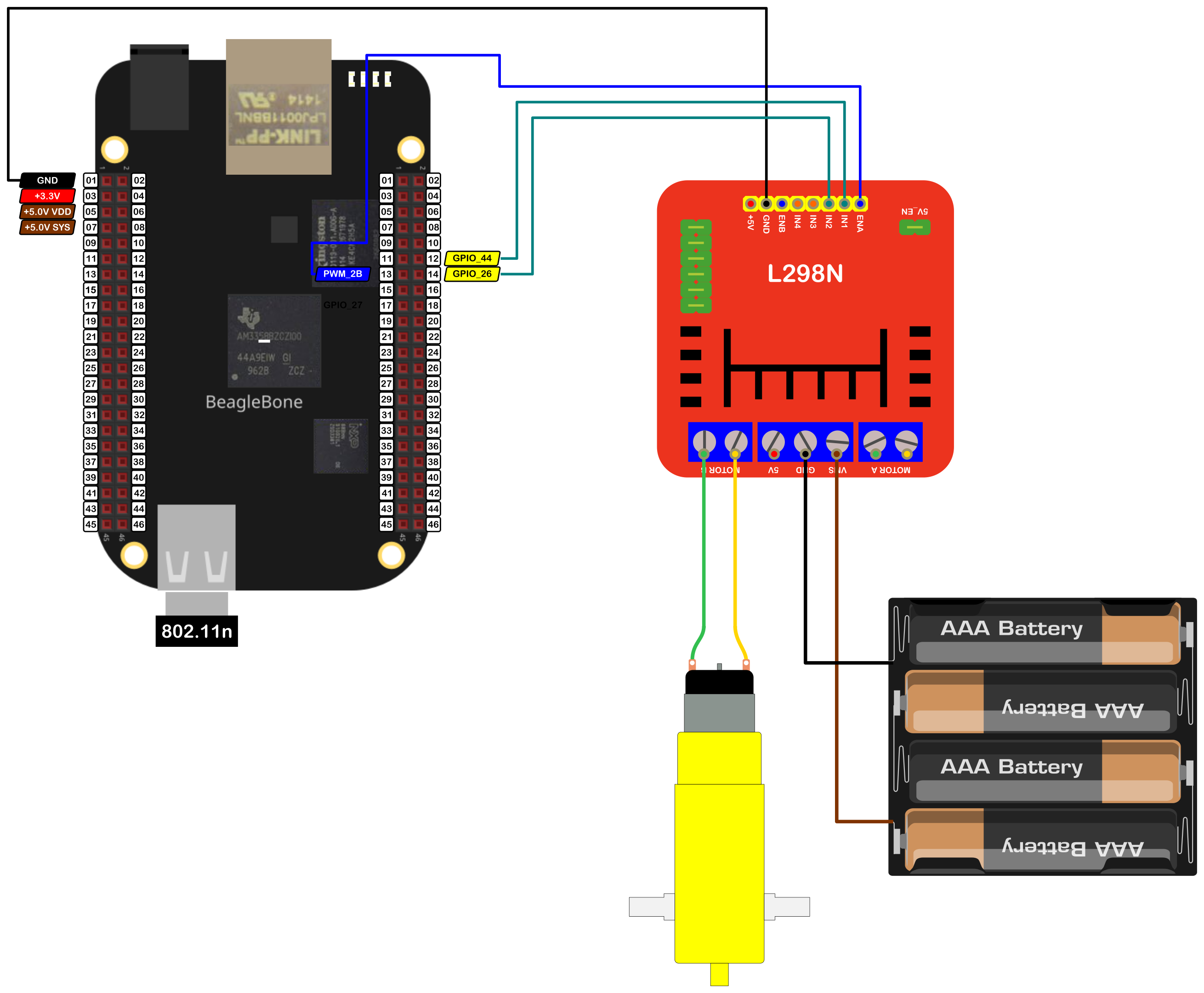
The components are:
- 1 DC Motor driver module L298N
- 1 DC Motor 5.0 - 6.0V
- 4 AA Batteries o 6 AA rechargeable batteries at 1.2V
- 1 Protoboard mini
- Jumpers male-male to make the connections
The pins used for control the motor are:
- GPIO P8_12 and P8_14 to control the motor rotation direction
- PWM P8_13 to control the speed
Coding
First, a DCMotor object is declared. For that, two GPIO and one PWM objects are declared with global scope to initialize the motor that will be driven.
The GPIOobjects are named AIN1 and AIN2, while the PWMobject is PWMA and are used to initialize the DCMotor object named MotorLeft which contains the methods to set the speed, the spin direction and to drive or stop the DC motor.
In this DCMotor object, the user can include a fourth boolean initialization parameter true/false to invert by software the motor direction rotation instead of inverting the motor’s jumpers physically.
1
2
3
4
5
6
7
// Declaring the pins for motor
GPIO AIN1 (P8_12);
GPIO AIN2 (P8_14);
PWM PWMA (P8_13);

// Declare the motor object
DCMotor MotorLeft (AIN1, AIN2, PWMA);
The DCMotorobject constructor is shown in the next listing:
1
2
3
4
5
6
7
8
9
10
11
12
13
14
15
16
17
18
19
20
21
22
23
24
25
26
27
28
29
// Overload Constructor
DCMotor::DCMotor (GPIO newInput1Pin,
                  GPIO newInput2Pin,
                  PWM newPWMPin,
                  bool newSwapSpinFlag) :
                  input1Pin(newInput1Pin),
                  input2Pin(newInput2Pin),
                  pwmPin(newPWMPin),
                  swapSpinFlag(newSwapSpinFlag)
{
  InitMotorPins();

  std::string message;
  std::string swapString {this->swapSpinFlag ? "True" : "False"};
  message = "\nMotor object with the next parameters / pins was created:\n" +
            std::string("\tIN1: ") + this->input1Pin.GetPinHeaderId() + "\n" +
            std::string("\tIN2: ") + this->input2Pin.GetPinHeaderId() + "\n" +
            std::string("\tPWM: ") + this->pwmPin.GetPinHeaderId() + "\n" +
            std::string("\tSwap Spin: ") + swapString + "\n\n";
  std::cout << RainbowText(message, "Gray");
}

// Private method to initialize the Pins
void DCMotor::InitMotorPins()
{
  // Set the right modes for the pins
  input1Pin.SetMode(OUTPUT);
  input2Pin.SetMode(OUTPUT);
}
This DCMotor object is used to initialize the L298N object. This inheritance structure has the goal to encapsulate the corresponding methods for any generic DC motor avoiding repeat code in the L298N object and focusing on the methods to drive / brake the DC motor, and not only one, but the two motors at the same time and in a different direction if it desired.
1
2
// Declare the L298N Module
L298N myL298NModule (MotorLeft);
The L298N object constructor is shown in the next listing:
1
2
3
4
5
6
7
8
9
10
11
12
13
14
15
16
17
18
19
// Overload constructor from DCMotor object for ONLY the MotorA
L298N::L298N (DCMotor& newMotorA) :
              MotorA (newMotorA)
{
  // Set the flags about which motors are used
  motorAisUsed = true;
  motorBisUsed = false;

  std::string message;
  std::string swapStringMotorA {this->MotorA.swapSpinFlag ? "True" : "False"};
  message = "\nTB6612FNG driver module with the next components / pins was created and activated:\n" +
            std::string("\tMotorA:\n") +
            std::string("\t\tAIN1: ") + this->MotorA.input1Pin.GetPinHeaderId() + "\n" +
            std::string("\t\tAIN2: ") + this->MotorA.input2Pin.GetPinHeaderId() + "\n" +
            std::string("\t\tPWMA: ") + this->MotorA.pwmPin.GetPinHeaderId() + "\n" +
            std::string("\t\tSwap Spin: ") + swapStringMotorA + "\n" +
            "\n\n";
  std::cout << RainbowText(message, "Light Red");
}
To make turn the DC motor, the method is L298N::DCMotor::Drive can be used. This receives two parameters:
- Speed in percentage, i.e. integer values between 100 and -100
- Time of the spin duration in milliseconds
A positive speed value sets the motor to turn in the CW direction, while, a negative speed value sets the motor to turn in the CCW direction.
1
myL298NModule.MotorA.Drive(speed,duration);
A positive speed value sets the motor to turn in the CW direction, while, a negative speed value sets the motor to turn in the CCW direction.
1
2
3
4
5
6
7
8
9
10
11
// Turn the motor in CW direction
for (int speed = 0; speed < 100; speed += 10)
  myL298NModule.MotorA.Drive(speed,1000);
for (int speed = 100; speed > 0; speed -= 10)
  myL298NModule.MotorA.Drive(speed,1000);

// Turn the motor in CCW direction
for (int speed = 0; speed > -100; speed -= 10)
  myL298NModule.MotorA.Drive(speed,1000);
for (int speed = -100; speed < 0; speed += 10)
  myL298NModule.MotorA.Drive(speed,1000);
The complete code for this application is shown in the next listing together with its corresponding execution output.
L298N_1.1.cpp
1
2
3
4
5
6
7
8
9
10
11
12
13
14
15
16
17
18
19
20
21
22
23
24
25
26
27
28
29
30
31
32
33
34
35
36
37
38
39
40
41
42
43
44
45
46
47
48
49
50
51
52
/******************************************************************************
L298N_1.1.cpp
@wgaonar
20/04/2021
https://github.com/wgaonar/BeagleCPP

- Move the motor each 1000 milliseconds increasing the speed 10%
  each time and then reversing it.
- Move the motor in the other direction each 1000 milliseconds increasing the
  speed 10% and then reversing it.

Class: L298N
******************************************************************************/

#include <iostream>
#include "../../../Sources/L298N.h"

using namespace std;

// Declaring the pins for motor
GPIO AIN1 (P8_12);
GPIO AIN2 (P8_14);
PWM PWMA (P8_13);

// Declare the motor object
DCMotor MotorLeft (AIN1, AIN2, PWMA);

// Declare the L298N Module
L298N myL298NModule (MotorLeft);

int main()
{
  string message = "Main program starting here...";
  cout << RainbowText(message,"Blue", "White", "Bold") << endl;

  // Turn the motor in CW direction
  for (int speed = 0; speed < 100; speed += 10)
    myL298NModule.MotorA.Drive(speed,1000);
  for (int speed = 100; speed > 0; speed -= 10)
    myL298NModule.MotorA.Drive(speed,1000);

  // Turn the motor in CCW direction
  for (int speed = 0; speed > -100; speed -= 10)
    myL298NModule.MotorA.Drive(speed,1000);
  for (int speed = -100; speed < 0; speed += 10)
    myL298NModule.MotorA.Drive(speed,1000);

  message = "Main program finishes here...";
  cout << RainbowText(message,"Blue", "White","Bold") << endl;

  return 0;
}
Se you in the next post.